
Introduction
I'm a nerd, and I tend towards dark places - thus my desk, where I keep my Printrbot, tends to be poorly lit. After getting very tired of using a flashlight to monitor the progress of my prints I decided to design and print a lighting solution that could be mounted to the Z-axis of the Printrbot.
I recently upgraded my Printrbot Simple Metal with Printrbot's X and Z axis upgrades...the new print area is huge, so I designed the lights to be larger than a standard Printrbot Simple Metal's print area of 150cm3. While this design doesn't require the Z-axis upgrade, it does need the x-axis upgrade...as the width of the mounting bracket and light "sled" is > 220mm.
Parts
The most expensive part (aside from the Printrbot of course) is the LEDs that are mounted in the "sled." For these, there are lots of places to find strip LEDs, including sites like eBay. But I like to be cheap, so I found some Automotive Accent Lights at WalMart in the Clearance aisle.

However you find them, some important characteristics to keep an eye out for:
- 12v input - this way you can hook them directly to an ATX PSU that you have powering the Printrbot (you DO have an ATX PSU, don't you?). Using automotive-based lights (typically) makes it easier, cause they're designed to plug straight into a 12v source. If they have the cigarette light adapter, check the adapter to see if there's any circuitry in there to step-down the power from the car's 12v source to 5v or something similar.
- Cut-to-length - you'll want to be able to trim them to the appropriate length. The "sled" is allows for about 210mm of length for the LEDs, not including the tail where the wires come out.
- Adhesive back - this will make sticking them to the sled easier - but you can also use some 2-sided foam mounting tape.
Aside from the LEDs, you'll need:
- Printrbot Simple Metal with X-axis upgrade and the Aluminum handle for the Z-axis
- (8) 10-12mm x 3mm hex cap screws
- A spare 4-pin molex connector to wire the LEDs to
- A soldering iron and some solder
- Some heat-shrink and heat gun, or electrical tape to protect the exposed wires
- Some zip-ties (optional)
- Some 2-sided foam mounting tape (optional)
Printing
The lights are separated into two pieces - the bracket that mounts to the Printrbot, and the light "sled" that holds the LEDs.
Download the .STL files from Thingiverse
Printing is fairly straightforward - whatever settings work well for your printer, for producing a large, flat-based print. No supports are necessary, but if they make you feel better, the "sled" may benefit from them a little if you have problems with > 1cm bridges.

Assembly
Start by threading the LED strips into the light sled to see where you need to trim them. Typically, cut-to-length led strips have lines on them where you should cut them - if not, a dead give away are the solder pads where the wire tails would be connected.

Make sure you're happy with the lengths, cut them and then thread them through into the sled, leaving the tails to stick out through the holes in the top of the sled.


Thread the wires through the channels.

You can screw the sled to the mounting bracket using 4 of the 3mm hex screws before threading the wires or after - your choice. But finish threading the wires through the channels on the mounting brakcet.


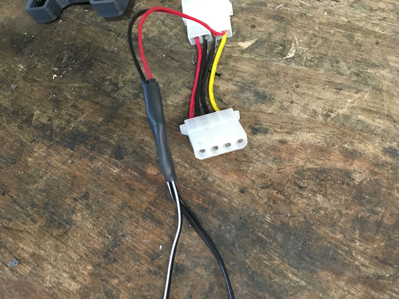
Now you'll need to cut-and-strip the ends of the leads to the LED strips, and also strip the leads to the Molex connector. I usually have a ton of these sitting around that have come with case fans, case accent lights, old adapters for powering hard drives etc. Here's one that I had left over from a fan adapter. You can just cut the 2 pin fan connector off to give you wires to connect the LED strips to.


You'll need to identify the positive/negative leads on the LED strip tails - in my case, the wires are both black - but the positive (12v) lead has a white strip. On the Molex connector, the red lead will be the positive (12v) connection, and the black will be the ground. Twist the 12v leads from the LEDs to the 12v (red) wire on the molex connector. Do the same for the ground leads to the black connector. Solder the leads together.

Optional: before you twist the leads together, I used two lengths of small-diameter heat shrink on the positive/negative leads of the Molex connector which will help protect the positive/negative connections. I also used a section of larger-diameter heat-shrink that will be slid over the two smaller sections, to keep everything in one nice package. Electrical tape could be used instead, but heat shrink is so much sexier.

Now use some zip ties to keep the wires nice and tidy. Or not...your choice.

Time to mount the lights! The mouting bracket has holes on both sides that line up with the 3mm holes in the aluminum mounting handle that goes on top of the Z axis of the Printrbot. Use 2 of the 3mm hex-cap screws on each side to mount the bracket.

Finally, plug the Molex connector into the ATX PSU, and you're done!

No comments:
Post a Comment